128x64 COG LCD Modules | BO12864E4
Model No. BO12864E4
- COG package
- Built-in controller ST7565S
- +3.3 V power supply
- 1/64 duty cycle
- On chip LCD booster
- Option LED B/L
數量
Description
BO12864E series:
- BO12864E3 : ST7567S
- BO12864E4 : ST7565S
Specification
Features
| Item | Dimension | Unit |
|---|---|---|
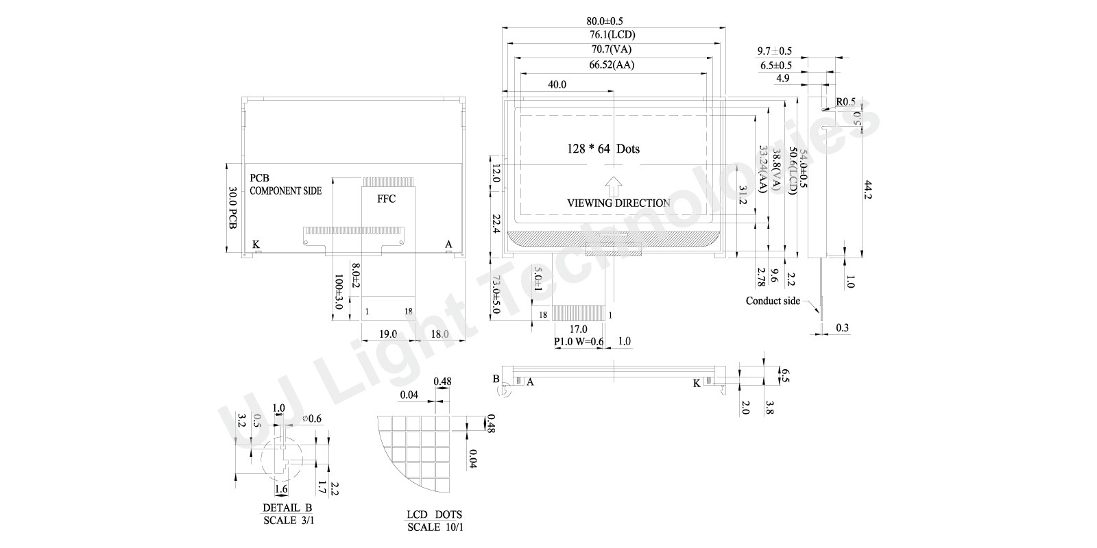
| Module dimension | 80.0 x 54.0 x 9.7 | mm |
| View Area | 70.7 x 38.8 | mm |
| Dot size | 0.48 x 0.48 | mm |
| Dot Pitch | 0.52 x 0.52 | mm |
Electrical Characteristics (Ta=25±2°C)
| Item | Symbol | Condition | Min | Typ | Max | Unit |
|---|---|---|---|---|---|---|
| Supply Voltage for Logic | VDD-VSS | - | 3.0 | 3.3 | 3.6 | V |
| Supply Voltage for LCD | V0-XV0 | Ta=25°C | 9.9 | 10.2 | 10.5 | V |
| Supply Current | IDD | VDD=3.3V | - | 0.5 | - | mA |
| LCM Surface Luminance (T=25°C) | L | ILED=120mA Display all OFF | 3.5 | 110 | - | cd/m2 |
Interface
| Pin | Symbol | Level | Function |
|---|---|---|---|
| 1 | VSS | - | GND |
| 2 | VDD | - | +5V (+3V option) |
| 3 | VO | - | DC/DC voltage converter
|
| 4 | /RES | H/L | When /RES is set to “L,” the settings are initialized. The reset operation is performed by the /RES signal level. |
| 5 | CS | H/L | This is the chip select signal |
| 6 | RS | H/L | This is connect to the least significant bit of the normal MPU address bus, and it determines whether the data bits are data or a command. R“H”: Indicates that D0 to D7 are display data. |
| 7 | /WR | H/L | Write signal |
| 8 | /RD | H/L | Read signal |
| 9~16 | DB0~DB7 | H/L | Data bus |
| 17 | A | - | Power supply for B/L (+) |
| 18 | K | - | Power supply for B/L (-) |