128x64 COG LCD 顯示模組 | UO12864E3
Model No. UO12864E3
- COG package
- Built-in controller ST7567S
- +3.3 V power supply
- 1/64 duty cycle
- On chip LCD booster
- Option LED B/L
數量
產品敘述
UO12864E 系列有兩款 COG IC 可供選擇:
- UO12864E3 : ST7567S
- UO12864E4 : ST7565S
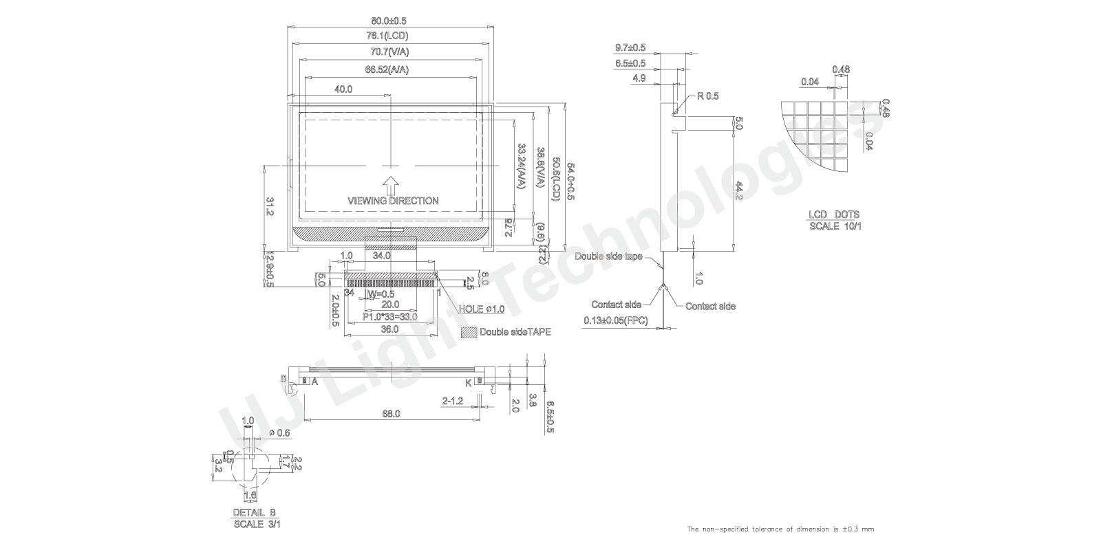
規格圖
產品規格
| Item | Dimension | Unit |
|---|---|---|
| Module dimension | 80.0 x 54.0 x 9.7 | mm |
| Active Area | 70.7 x 38.8 | mm |
| Dot size | 0.48 x 0.48 | mm |
| Dot Pitch | 0.52 x 0.52 | mm |
電氣特性 (Ta=25±2°C)
| Item | Symbol | Coondition | MIn | Typ | Max | Unit |
|---|---|---|---|---|---|---|
| Supply Voltage For Logic | VDD-VSS | - | 3.0 | 3.3 | 3.6 | V |
| Supply Voltage For LCD | V0-XV0 | Ta=25°C | 9.9 | 10.2 | 10.5 | V |
| Supply Current | IDD | VDD = +3.3V | - | 0.5 | - | mA |
| LCM Surface Luminance (Ta=25°C) | L | ILED=40mA Display all OFF | 3 | 4 | - | cd/m2 |
Pin功能定義
| PinSDA | Symbol | Level | Function |
|---|---|---|---|
| 1 | /CS1 | I | This is the chip select signal |
| 2 | /RES | I | When /RES is set to “L,” the settings are initialized. The reset operation is performed by the /RES signal level. |
| 3 | A0 | I | It determines whether the access is related to data or command. A0=“H” : Indicates that signals on D[7:0] are display data. A0=“L” : Indicates that signals on D[7:0] are command. |
| 4 | /WR, R/W | I | /WR, 8080 mode. R/W, 6800 mode. |
| 5 | /RD, E | I | /RD, 8080 mode. E, 6800 mode. |
| 6~13 | D0(SCL) D1(SDA) D2~D7 | I/O | When using serial interface: 4-line SPI,3-line SPI or I2C serial interface D[0]=SCL: Serial clock input. ID[0:3] can be read 4-bit ID only for serial interface from D[4:7]. |
| 14 | VDD | 3.3V | Power supply for logic |
| 15 | VSS | 0V | Power supply for logic GND |
| 16~18 | NC | - | Not used. |
| 19 | V0 | O | V0 is the LCD driving voltage for common circuits at negative frame. |
| 20 | XV0 | O | XV0 is the LCD driving voltage for common circuits at positive frame. |
| 21~24 | NC | - | Not used. |
| 25 | VG | O | VG is the LCD driving voltage for segment circuits. |
| 26~30 | NC | - | Not used. |
| 31 | C86 | I | C86 selects the microprocessor type in parallel interface mode. |
| 32 | PSB | I | PSB selects the interface type: Serial or Parallel. |
| 33 | SI2 | I | SI2 selects the interface type: I2C serial interface or not |
| 34 | NC | - | Not used. |